Beyond the Racetrack: The Perfect Formula for a Ventilator
Interview with Simone Resta
By Elettra Preosti
As published in Berkeley Scientific Journal Volume 25, Issue 1, Bonds pp. 20-24
Simone Resta is Head of Chassis Area at Scuderia Ferrari, the Formula 1 racing team of luxury Italian automobile manufacturer Ferrari. He obtained a master’s degree in Mechanical Engineering from the University of Bologna. Shortly after, he began his career in Formula 1 with Minardi’s automobile team, joining Scuderia Ferrari as a member of the Design Office three years later in 2001. Apart from a brief experience with Alfa Romeo that lasted from August 2018 to May 2019, he has remained with the team for nearly 20 years, where he has worked on some of the most meaningful projects of his career. In this interview, we discuss Simone Resta’s work on leading a team of engineers from Scuderia Ferrari to design the FI5 pulmonary ventilator in collaboration with Istituto Italiano di Tecnologia (ITT) to combat COVID-19.
BSJ: How did your early experiences growing up in Italy shape your interest in Mechanical Engineering, and what led you to pursue a career in Formula 1?
SR: I was born and raised in Imola, an area with a lot of Formula 1 history. You might know that there is a circuit, the Dino and Enzo Ferrari circuit, in Imola. So, Formula 1 was a big part of the local culture growing up, making it a passion of mine since I was a child. Additionally, when I was younger, my dad owned a small laboratory that specialized in precision mechanics. During the summers, I would help him by working in the laboratory. I was working with my hands, tools, machines, and so on to develop mechanical parts. That was probably where my passion for mechanics started to grow. Eventually, I went to university to pursue a degree in Mechanical Engineering. A career in Formula 1 brought my passions for mechanical engineering, cars, and Formula 1 together.
BSJ: How did the collaboration between Ferrari and IIT to design pulmonary ventilators in response to COVID-19 begin?
SR: Ferrari and IIT are two leading institutions in Italy, and there is actually a running collaboration between these two entities. This time, IIT asked Ferrari to support them on the FI5 Pulmonary Ventilator Project as they were looking to fast-track this project. The goal was to design and produce something very, very quickly in response to the COVID-19 pandemic that was, at the time, not only growing rapidly in Italy, but all over the world.
BSJ: What are some key characteristics of the FI5 Pulmonary Ventilator that are beneficial to patients with COVID-19?
SR: I think that the most important characteristics of this product are its affordable production costs, accessibility, reliability, and simplicity. To begin, the product is simple and reliable, equipped with the minimum number of functions required to fit its overall purpose. This helps lower the cost of production of the FI5 Pulmonary Ventilator, which is one order of magnitude less than ventilators currently available on the market. Additionally, its components can be easily purchased or manufactured locally. This is especially significant, given the fact that we created this ventilator as an open source project. Thus, our product is something that is very easy to produce by anyone worldwide who is interested or in need.
Despite its minimum number of functions, the FI5 ventilator still has multiple applications as it can be used not only with a standard, non-invasive mask, but also a full face mask or helmet, which can be more comfortable for patients. In other words, the product was designed to be as generic as possible (given cost constraints) in order to satisfy multiple uses.
BSJ: What is the general structure of the FI5 Pulmonary Ventilator, and how does it work to effectively pump oxygen into a patient’s lungs?
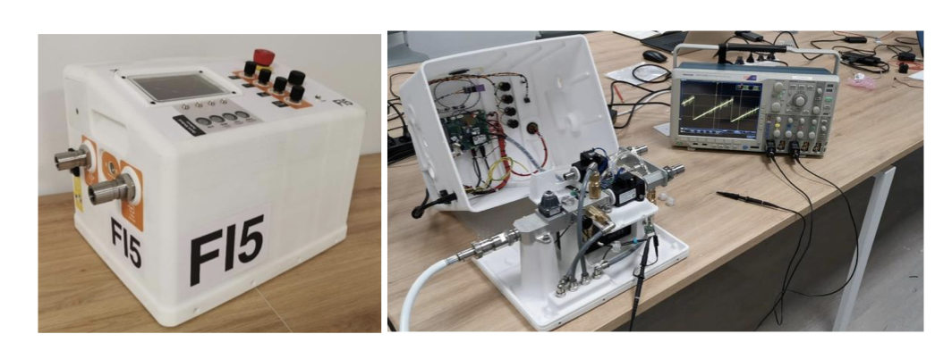
SR: The ventilator is composed of a pneumatic circuit controlled by valves and managed by a computer. Operators can program the system through several interfaces in order to adjust the system’s frequency, released mass flow rate, and composition. This effectively puts an Intensive Care Unit (ICU) inside the FI5 ventilator. The ventilator then manages the air flow from hospital lines. It is important to note, however, that the ventilator has been designed in such a way that it must be connected to a hospital line for air; it can not be used off-site as it is not a fully autonomous system. So, ultimately, it is a machine that takes the fluids from the hospital lines and releases them using parameters (frequency, amplitude, and composition) controlled by the provider.
Figure 1: Full prototype of the FI5 Ventilator (left). Open enclosure of the FI5 Ventilator with details on the positioning of the electronics (right) (2).
BSJ: Ferrari engineers focused on designing the pneumatic and mechanical components of the FI5 Pulmonary Ventilator. What are the three pneumatic stages (pneumatic phases) of the ventilator, and what role does each play in the overall design of the ventilator?
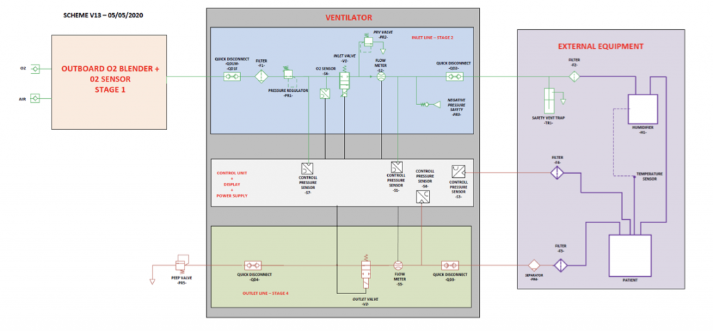
We applied our knowledge from designing Formula 1 cars to determine the three pneumatic stages of the ventilator. The first pneumatic stage, Stage 1, represents the interface between the ventilator and the hospital line responsible for delivering oxygen. This stage modulates the level of oxygen delivered to patients by adjusting the ratio of oxygen to air, which is a mixture of nitrogen, oxygen, and other gases. It is external to the ventilator and can be customized as needed. In contrast, Stage 2 is physically inside the ventilator. It consists of the main inlet line, which includes filters, a pressure regulator, an electrovalve to control inhalation, sensors, and safety pressure relief valves. Finally, Stage 3 refers to the outlet line, which simply comprises an outlet valve that controls the exhalation phase. Determining the structure of these three stages was one of the most critical, but rewarding aspects of this project.
Figure 2: Pneumatic scheme of the three pneumatic phases of the ventilator (2).
BSJ: One of the main goals in designing the FI5 Pulmonary Ventilator was to minimize the cost of production relative to existing ventilators. How did you achieve this goal?
SR: The guiding principle throughout this project has been to identify the minimum required functions of the ventilator (with respect to a typical hospital’s needs) to minimize production cost. In order to define these requirements, we collaborated with hospitals and doctors like Dr. Forgione. So, that has been the first stage and one of the most important ones. We were further able to reduce the cost of production of the FI5 Pulmonary Ventilator through our choice of components; many of the final components are produced by Italian companies, like Camozzi Automation, which specializes in pneumatic parts. Furthermore, using technologies like 3D printing to produce mechanical components has also helped in minimizing the cost of production. All together, this allowed us to reach our target cost as the FI5 pulmonary ventilator costs only about a tenth of a normal ventilator.
BSJ: You minimized the number of custom components present in the F15 pulmonary ventilator in order to reduce the production cost. What off-the-shelf parts, available globally, were used in place of custom components?
SR: Several parts of the ventilator can be manufactured worldwide, and many three-dimensional parts that can be produced using 3D printing. Some of these components include the valves, CPU, and screen. Using commercially-available parts that can be mass produced and obtained everywhere has really allowed our project to be easily accessible worldwide. For example, our product is being developed by several Mexican firms as well as several other Latin American companies.
BSJ: Ferrari also played a role in running dynamic simulations to develop the FI5 Pulmonary Ventilator. Can you begin by describing the Simulink model?
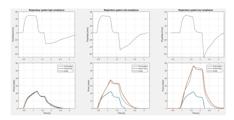
SR: The Simulink model has three important features. The first feature consists of three mathematical models of the human lungs (soft, medium, and stiff), which essentially simulate the mechanics of lung ventilation. It is the most important part of the Simulink model.
Figure 3: The three mathematical models of the human lungs characterized by three different compliance values: high compliance (stiff), mid compliance (medium), and low compliance (soft) (2).
The next feature is the main flow line, which consists of controlled valves, pressure relief valves, quick disconnect, and capacitive and resistive pipes. In order to properly test the response of the system, compliance of the lungs, and energy losses, we created a model of all of the pipes, pressure drops, valves, etc. This model included controls to evaluate the valves’ performance under desired pressure dynamics.We also added a section to our model that computes CO2 accumulation near the patient’s mouth, both when the patient is wearing a mask or helmet. This allowed us to implement strategies that prevented buildup of a dangerous concentration of CO2 (>2%).
Lastly, the Simulink model includes a model for the Air/Oxygen mixing device—so that we can reach the target O2 percentage—and the pressure regulator, which allows the inlet valve to operate at a controlled pressure.
BSJ: How were you able to model the behavior of human lungs, taking into account three different values of compliance (soft, medium, and stiff)? How were these different models used to develop the inlet and outlet valves of the ventilator?
SR: In our model for the behavior of human lungs, the human lungs have been schemed as a viscoelastic model with an elastance factor that simulates the chest wall. It is easy to model this kind of system using a combination of springs and dampers.
To aid us in defining our parameters, we found a paper that demonstrates the extreme cases of human lung response to equivalent mass flow boundaries. As you can imagine, the pressure inside of a human lung varies a lot between a young child and a two meter tall basketball player. And, the elasticity, capacity, and resistance between a healthy person’s lungs to the lungs of a person who suffers from cystic fibrosis will also be different. So, we had to take all of these factors into consideration.
To accomplish this, in each phase of the respiratory cycle, we selected the worst case lung characteristic and checked all of the components to guarantee that there were no issues. For instance, the exhalation valve must be permeable enough not to affect natural exhalation. This is because a stiffer lung will increase the flow rate through the exhalation valve causing the patient’s condition to worsen. On the other hand, the inhalation phase works in the opposite way: the lower the elasticity, which is associated with a higher tidal volume, the higher the required flow needed to reach target mouth pressure will be. So, we used the high compliance model of the lung to design the outlet valve and the low compliance model of the lung to design the inlet valve. However, while the valves have been defined in this way—incorporating worst case lung characteristics—we also had to verify our system worked in the opposite scenario—best lung characteristics—to certify the quality of both hardware and control and made sure dynamics were satisfied under all conditions.
BSJ: How does the Air/Oxygen mixing device reach the target O2 percentage, and how is that target percentage determined?
Because the Air/Oxygen mixing device is supplied by the provider, for simplicity, we assumed the most straightforward design. This design is one in which the mixing device can be operated completely manually and the target O2 percentage can be reached by adjusting the two throttle valves controlling the air and oxygen lines. The target O2 is then determined by the provider when evaluating the readings on the patient’s blood oxygenation.
BSJ: How does the pressure regulator work to allow the inlet valve to operate at a controlled pressure?
SR: The pressure regulator consists of a pressure loss, which is a function of the inlet pressure; the pressure loss increases by the same amount as the inlet pressure in order to ensure a nearly constant outlet pressure. It is a necessary component since it allows the inlet valve to work in constant conditions, independent of the hospital pressure line. Every control parameter has been optimized to get the best valve performance in following target mouth pressure, and this allows us to be sure that the valve always operates at its best.
BSJ: What are the permeability targets for various components of the ventilator, and why are they important in determining the robustness of the system?
SR: The main sources of pressure loss stem from the HEPA filter and quick disconnect. However, we still want to ensure that pressure losses are as low as possible throughout the system in order to allow for correct system functionality. In particular, in the flow upstream to a patient’s mouth, there are two pressure relief valves, a mechanical component inside the ventilator, and an external water bottle. If the pressure drop between the two valves is too high, it may be impossible to reach target mouth pressure. Moreover, there is a filter located between the patient and the outlet valve. If the pressure loss here is too high, it can impede the exhalation dynamics of the patient. This would lead to high frequency respiratory cycles—almost similar to hyperventilation.
BSJ: What options have been simulated in order to determine the best solution to lower CO2, and which one was most successful?
SR: First, because we know that CO2 accumulation is a function of exhalation volume around the patient’s mouth, we had to consider different strategies for both the mask (0.5L), and helmet (8L) scenarios. Our initial strategy was to keep both the inlet and outlet valves open simultaneously during different cycle phases; for example, at the beginning or end of the exhalation phase. We next tried simulating a constant inlet valve flow-by. We found that this was the easiest and most efficient way to reduce CO2 concentration since it allows for continuous action and does not change the shape of the mouth pressure curve by much. In other words, the inlet valve flow-by method applies a constant positive pressure to the patient’s mouth, which in turn naturally decreases the tidal volume. Our control can then automatically detect and modify the target pressure curve in order to keep the inhaled volume constant.
BSJ: What are the four mechanical devices that define the flow/pressure level on the patient’s mouth, and what simulations were carried out to ensure that they would not fail?
SR: The four devices are the pressure regulator, inlet valve, pressure relief valve, and bottle valve. We performed simulations in order to limit the negative impact a failure in each component could have on the entire ventilator. For example, in the worst case scenario that our bottle valve is either damaged or not fitted, we want to ensure that the functionality and performance of the ventilator are guaranteed even if one of the remaining components also fails. If, for instance, the pressure regulator also fails, control parameters would be set in place to automatically adjust for the failure If, instead, both the inlet and bottle valves fail, the check valve will prevent an unmitigated increase in the pressure (exerted) on a patient’s mouth.
BSJ: What were some of the major challenges that you encountered in designing the F15 Pulmonary Ventilator?
SR: Certainly, we faced challenges in understanding how to approach a project like this from scratch. The biggest challenge we initially faced was how to adapt our models and parameters to effectively study the lungs. This is where our collaboration with hospitals and doctors came in. We later faced other challenges in terms of cost. In tackling this issue, we had to thoroughly consider the best cost engineering practices when evaluating the proposed method of manufacturing certain parts, 3D printing in general, etc. On top of that, not only did we have to finish this entire project in just a few weeks, but we were also in lock-down. This meant that we had to fundamentally adjust our mindset while adapting to a new, virtual mode of interaction.
BSJ: How were you able to apply the technology used in developing Formula 1 cars to design the FI5 pulmonary ventilators?
SR: The project itself is quite different from what we normally work on. However, the technologies on both sides share a lot of common points, so we were able to apply our knowledge from designing F1 cars and adapt it to a completely new product. Similar to vehicular design, we used simulation models of the proposed ventilator in order to understand what to optimize prior to production. Moreover, while the design of F1 cars revolve primarily around hydraulic applications, there were a few pneumatic applications that proved helpful in orienting our approach to designing the FI5 ventilator.
The FI5 ventilator also relies on the usage of 3D printing and CNC machines, practices that are rapidly becoming more widespread in the F1 business. Cost engineering is also becoming more and more relevant in the F1 business, so we were able to use some of our cost engineering practices to minimize the cost of the FI5 ventilator.
BSJ: What analysis is currently being done to determine what further developments can be made towards improving the performance of the FI5 pulmonary ventilators?
SR: Currently, the effort, driven by IIT, is mostly centered around ensuring that the product is available and can be easily adopted worldwide. The main focus of the effort is not so much in developing the project itself, but rather in making sure that the project becomes homologated and certified in hospitals. In this way, it can be used in many developing countries, and in fact, this initiative is taking off in some South American countries. We are currently supporting IIT on that.
BSJ: What other initiatives has Ferrari taken to combat the spread of COVID-19 not only in Italy, but throughout the world?
SR: First, Ferrari has launched an incredible, large-scale initiative called Back on Track. The goal of this project is to protect employees and their families during the COVID-19 pandemic as they return to both the factory and the race circuit. For instance, in order to gauge the safety risk of reopening the workplace, Ferrari distributed blood tests to both employees and their families.
Ferrari has also contributed financially to the fight against COVID-19. We were able to double our investment in COVID-19 research through funds from our customers. As opposed to accepting cash back for cancelled events, they requested that we donate these funds. With this money, we were able to donate an ambulance to a local hospital in Modena. Additionally, the entire Agnelli family, which controls Ferrari, has made several donations in response to the COVID-19 pandemic.
So, Ferrari is fully committed to the fight against the virus, with FI5 being one of the most important contributions we have made. The project itself very much originated from those in Scuderia Ferrari, who, while in lockdown, were able to realize this completely novel project. We did not want to profit off this project. Rather, we were very happy to bring our efforts beyond the racetrack, and we are determined to do anything we can to contribute to the fight against COVID-19 around the globe.
BSJ: Thank you so much for taking the time to meet with us.
SR: It was my pleasure. I would also like to thank all of my colleagues at Scuderia Ferrari, who have played a critical role in designing the FI5 Pulmonary Ventilator. I would especially like to thank Maurizio Bocchi, Luca Bottazzi, Luca Brunatto, Marco Civinelli, Marco Gentili, Corrado Onorato, Federico Rossi, and Bruno Petrini.
References
- Simone Resta [Photograph]. https://www.ferrari.com/en-EN/formula1/simone-resta
- Maggiali, et al. (2020). FI5 Ventilator Overview. Istituto Italiano di Tecnologia. https://multimedia.iit.it/asset-bank/assetfile/15783.pdf
